
Panel Designing & AutoCAD
Duration: 3 Months
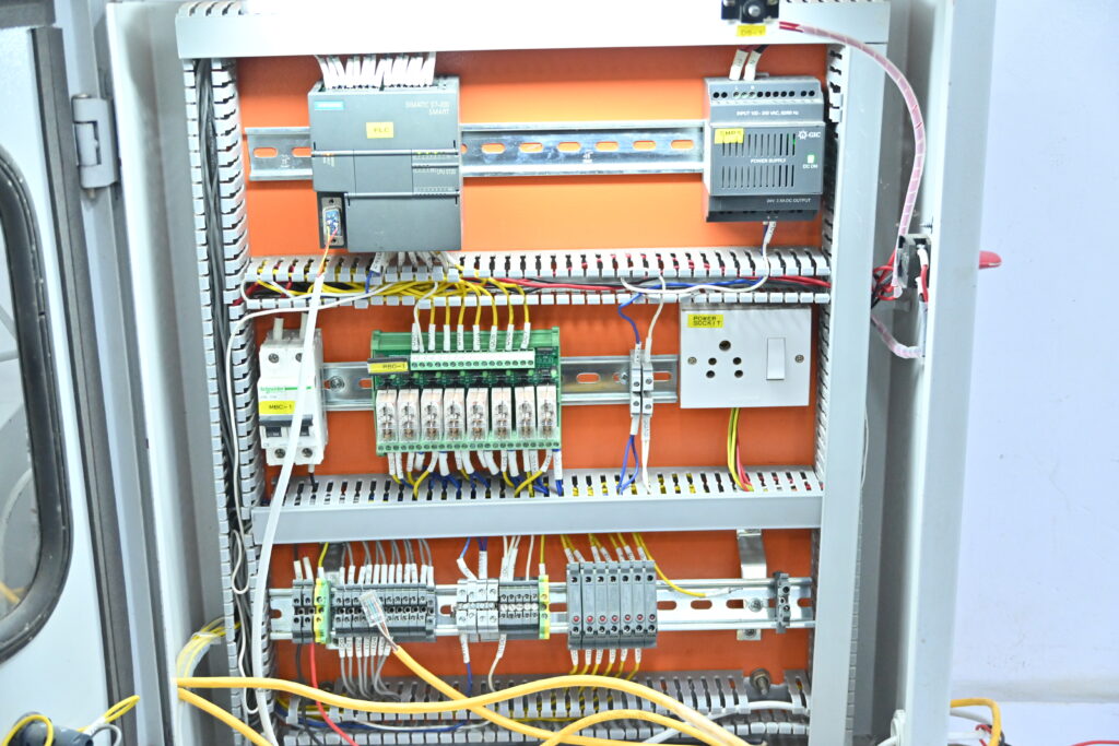
This course teaches how to design electrical control panels used in industrial automation. It includes both theoretical concepts and hands-on practice in creating schematics using AutoCAD Electrical software. You’ll learn everything from panel layout, cable selection, and protection devices to designing complete wiring diagrams.
Modules Covered:
Panel Design Using Electrical AutoCAD Course Syllabus
Module 1: Introduction to Electrical Panel Design
-
-
-
Overview of Electrical Panels and their Functions
-
Types of Electrical Panels (Control Panels, Distribution Panels, Motor Control Centers, etc.)
-
-
Importance of Panel Design in Industrial Automation
-
Basic Terminology in Electrical Panel Design
-
Circuit Breakers, Fuses, Contactors, Relays, Switches, Busbars
-
-
Introduction to Electrical Symbols and Standards
-
IEC, ANSI, DIN, UL Standards for Panel Design
-
-
Safety Standards in Electrical Panel Design
-
-
Module 2: Introduction to AutoCAD and Electrical AutoCAD
-
-
-
Overview of AutoCAD Interface
-
Navigating AutoCAD Workspace
-
Layers, Blocks, and Templates
-
-
Introduction to Electrical AutoCAD
-
Features of Electrical AutoCAD vs. Standard AutoCAD
-
Setting up Electrical AutoCAD Workspace for Panel Design
-
-
Electrical AutoCAD Tools and Commands
-
Tools for Wiring Diagrams, Single Line Diagrams, and Panel Layouts
-
Insert Electrical Components (Circuit Breakers, Switches, etc.)
-
-
-
Module 3: Basic Electrical Design Concepts
-
-
-
Understanding Electrical Schematics and Diagrams
-
Schematic Diagrams, Wiring Diagrams, and Layout Diagrams
-
-
Components of a Typical Electrical Panel
-
Main Breaker, Power Supply, Busbars, Panel Enclosures
-
HMI, VFD, PLC Integration in Panels
-
-
Power Distribution and Circuit Protection
-
Protection Relays, Fuses, MCCBs, and Contactors
-
-
Understanding the Role of Electrical Drawings in Panel Design
-
Floor Plans, Wiring Diagrams, and Control Schematics
-
-
-
Module 4: AutoCAD Electrical Components and Symbols
-
-
-
Creating and Using Electrical Blocks in AutoCAD
-
Predefined Electrical Symbols and Blocks in AutoCAD
-
Customizing Electrical Blocks for Panel Design
-
-
Wiring Diagrams in Electrical AutoCAD
-
How to Draw and Label Electrical Circuits
-
Using Electrical AutoCAD’s Circuit Builder and Schematic Tools
-
-
Creating and Managing Electrical Components
-
Inserting Circuit Breakers, Fuses, Relays, and Disconnects
-
Managing Connections and Power Paths
-
-
Symbol Libraries and Catalogs in Electrical AutoCAD
-
-
Module 5: Panel Layout Design in AutoCAD
-
-
-
Setting Up Panel Layout in Electrical AutoCAD
-
Using Templates for Panel Layouts
-
Drawing and Dimensioning the Physical Panel Layout
-
-
Placing Electrical Components in the Panel
-
Mounting Breakers, Contactors, Switches, PLCs, and Other Components
-
Creating Panel Door Layouts (Door Schematic, HMI Placement, etc.)
-
-
Cable Tray Routing and Layouts
-
Understanding Cable Management in Panels
-
-
Power Distribution and Grounding Considerations
-
Designing Busbars, Grounding, and Wiring in the Panel
-
-
-
Module 6: Creating Schematic Diagrams and Wiring Diagrams
-
-
-
Creating One-Line and Two-Line Diagrams for Panel Design
-
Generating Power and Control Wiring Diagrams in AutoCAD
-
Creating Ladder Diagrams for Relay Logic and Control Circuits
-
Managing Electrical Panel Wiring in Electrical AutoCAD
-
Adding and Labeling Wires, Conduits, and Cable Types
-
Using AutoCAD’s Automatic Wire Numbering Tools
-
-
Creating Panel Circuit Lists and Bill of Materials (BOM)
-
-
Module 7: Electrical AutoCAD for Panel Protection and Control
-
-
-
Designing Protection Circuits for Electrical Panels
-
Circuit Protection (Fuses, Breakers, MCCBs, etc.)
-
Protection Relays and Control Circuit Design
-
-
Control Panel Wiring Design and PLC Integration
-
Designing Control Wiring for PLC and HMI Connections
-
Integrating VFDs and HMIs into Control Panels
-
-
Creating Control Schematics for Start/Stop Circuits
-
Overload Protection, Interlocks, and Safety Circuits
-
-
-
Module 8: Automation Integration in Electrical Panel Design
-
-
-
Incorporating Automation Components into Electrical Panel Design
-
PLC, SCADA, VFD, and Servo Motors
-
-
Understanding Control Logic and Integration
-
Ladder Logic for Motor Control Panels
-
Communication with External Devices (Field Devices, Sensors)
-
-
Using AutoCAD to Design Panels for Automation Systems
-
Integrating PLC Inputs/Outputs, Control Relays, and Contactors
-
Designing I/O Terminals and Field Wiring
-
-
-
Module 9: Design Review, Documentation, and Finalizing Panel Layout
-
-
-
Reviewing Panel Designs for Compliance and Safety
-
Verifying Design Against Standards and Client Specifications
-
Quality Checks for Panel Design
-
-
Documentation of Electrical Panel Design
-
Preparing Detailed Panel Layout Drawings
-
Generating Panel Schematic Drawings, Single-Line Diagrams, and Wiring Diagrams
-
Creating a Complete Panel Design Package (Including BOM, Wiring List)
-
-
Finalizing the Design and Making Design Modifications
-
Revision Control and File Management in Electrical AutoCAD
-
-
-
Module 10: Practical Project and Case Studies
-
-
-
Designing a Complete Electrical Panel for a Real-World Application
-
Industrial Motor Control Panel, Distribution Panel, or MCC
-
Creating Complete Electrical Layouts, Wiring Diagrams, and Bill of Materials
-
-
Case Study Analysis
-
Reviewing Electrical Panel Designs for Various Industrial Applications
-
Design Modifications Based on Specific Industry Needs (e.g., HVAC, Water Treatment, Manufacturing)
-
-
-
Conclusion and Certification
-
-
-
Final Project Presentation: Students will present their designed panels and drawings to the instructors.
-
Review of Key Concepts and Techniques
-
Certification of Completion for Electrical AutoCAD Panel Design Course
-
-
This syllabus ensures that students receive a comprehensive understanding of electrical panel design, using Electrical AutoCAD as the core tool. They’ll gain hands-on experience with the full design process, from initial schematics to final panel layout and documentation.